Tag: arduino

  • Arduino Laser Tag Update #3

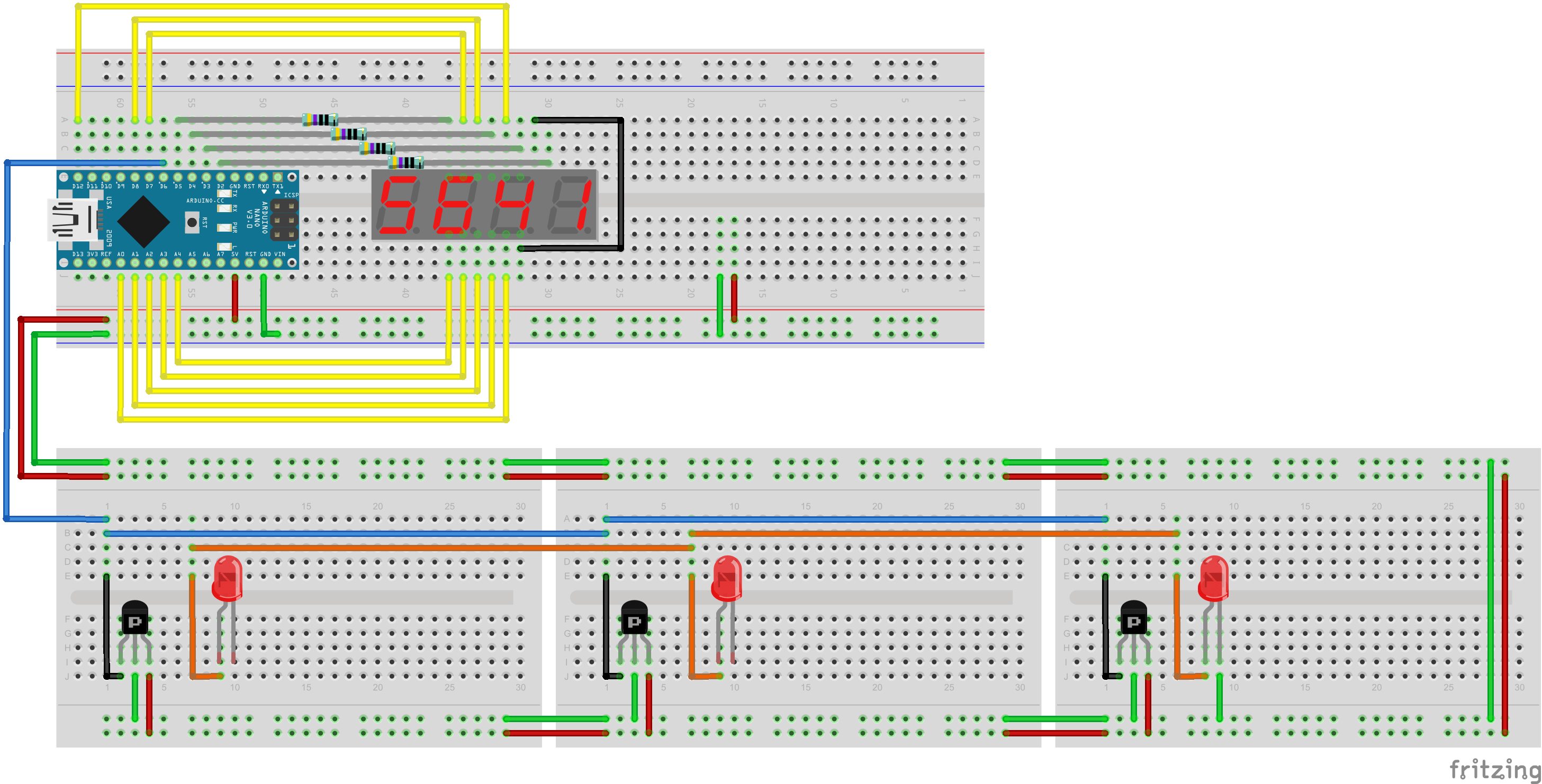
    Hardware Testing and Refinement

    One of the issues I encountered with my proposed setup in Update #1 is that the LED segments will periodically dim. This was because I only used one resistor to power all 7 segments (8 including the dot) in parallel. This would work if all LEDs in the display were manufactured the same way. However, it’s more likely that some LEDs draws more current than the others causing some segments to become slightly brighter while the others dim. The better way to connect the LEDs is to have a resistor after each one. I used a 2K Ω resistor after each segment so that the current flowing through each LED remains low.

    This hardware configuration worked out a lot better for me. All the LEDs remained at a constant brightness. I also managed to get the IR Sensor an the IR LED working at the same time. My test code for this setup is shown below.

    #include <IRremote.h>
     
    #define RECV_PIN 2
     
    #define DIGIT_1 12
    #define DIGIT_2 10
    #define DIGIT_3 9
    #define DIGIT_4 6
     
    #define SEG_A 7
    #define SEG_B 11
    #define SEG_C 15
    #define SEG_D 17
    #define SEG_E 18
    #define SEG_F 8
    #define SEG_G 14
    #define SEG_DOT 16
     
    IRrecv irrecv(RECV_PIN);
    IRsend irsend;
     
    decode_results results;
     
    int x = 1;
     
    void setup()
    {
      irrecv.enableIRIn(); // Start the receiver
       
      Serial.begin(9600);
       
      pinMode(13, OUTPUT);
       
      pinMode(SEG_A, OUTPUT);
      pinMode(SEG_B, OUTPUT);
      pinMode(SEG_C, OUTPUT);
      pinMode(SEG_D, OUTPUT);
      pinMode(SEG_E, OUTPUT);
      pinMode(SEG_F, OUTPUT);
      pinMode(SEG_G, OUTPUT);
      pinMode(SEG_DOT, OUTPUT);
       
      pinMode(DIGIT_1, OUTPUT);
      pinMode(DIGIT_2, OUTPUT);
      pinMode(DIGIT_3, OUTPUT);
      pinMode(DIGIT_4, OUTPUT);
       
      digitalWrite(SEG_A, LOW);
      digitalWrite(SEG_B, LOW);
      digitalWrite(SEG_C, LOW);
      digitalWrite(SEG_D, LOW);
      digitalWrite(SEG_E, LOW);
      digitalWrite(SEG_F, LOW);
      digitalWrite(SEG_G, LOW);
      digitalWrite(SEG_DOT, LOW);
       
      delay(250);
    }
     
    void loop() {
       
      digitalWrite(DIGIT_1, HIGH);
      digitalWrite(DIGIT_2, LOW);
      digitalWrite(DIGIT_3, LOW);
      digitalWrite(DIGIT_4, LOW);
       
      delay(x);
       
      digitalWrite(DIGIT_1, LOW);
      digitalWrite(DIGIT_2, HIGH);
      digitalWrite(DIGIT_3, LOW);
      digitalWrite(DIGIT_4, LOW);
       
      delay(x);
       
      digitalWrite(DIGIT_1, LOW);
      digitalWrite(DIGIT_2, LOW);
      digitalWrite(DIGIT_3, HIGH);
      digitalWrite(DIGIT_4, LOW);
       
      delay(x);
       
      digitalWrite(DIGIT_1, LOW);
      digitalWrite(DIGIT_2, LOW);
      digitalWrite(DIGIT_3, LOW);
      digitalWrite(DIGIT_4, HIGH);
       
      delay(x);
       
      if (irrecv.decode(&results)) {
        irrecv.resume(); // Receive the next value
         
        digitalWrite(13, HIGH);
         
      }else{
        digitalWrite(13, LOW);
      }
       
      if (Serial.read() != -1) {
         
        digitalWrite(DIGIT_1, LOW);
        digitalWrite(DIGIT_2, LOW);
        digitalWrite(DIGIT_3, LOW);
        digitalWrite(DIGIT_4, LOW);
         
        for (int i = 0; i < 3; i++) {
          irsend.sendSony(0xa90, 12); // Sony TV power code
          delay(40);
        }
         
        irrecv.enableIRIn();
      }
       
    }
  • Arduino Laser Tag Update #1

    IR Sensor & 7 Segment Display Initial Testing

    As part of the prototype for laser tag project, I’ve put together a Universal IR Infrared Receiver TL1838 VS1838B working in conjunction with a 4 digit 7 segment display I brought from Aliexpress. I am working towards building a testing platform to something similar to the schematic I’ve drawn below.

    We decided to go with a 4 digit display for flexibility in game programming. Mostly likely, the first two digits will be used for health and the last two will be used for ammo. The three IR Sensors on the bottom with their respective LEDs will eventually be attached on to a vest and linked back up to the gun. The IR sensors were tested with the Arduino Nano and the IR detector library from Ken Shirriff’s Blog. It was successful in detecting my remote control from a distance of more than 10 meters away. The testing code for the IR sensor and the 7 segment display is shown below.

    #include <IRremote.h>
     
    int RECV_PIN = 6;
     
    IRrecv irrecv(RECV_PIN);
     
    decode_results results;
     
    int x = 1;
     
    void setup()
    {
    irrecv.enableIRIn(); // Start the receiver
     
    pinMode(13, OUTPUT);
     
    pinMode(12, OUTPUT);
    pinMode(8, OUTPUT);
    pinMode(7, OUTPUT);
    pinMode(14, OUTPUT);
    pinMode(15, OUTPUT);
    pinMode(16, OUTPUT);
    pinMode(17, OUTPUT);
    pinMode(18, OUTPUT);
     
    pinMode(2, OUTPUT);
    pinMode(3, OUTPUT);
    pinMode(4, OUTPUT);
    pinMode(5, OUTPUT);
     
    digitalWrite(12, LOW);
    digitalWrite(8, LOW);
    digitalWrite(7, LOW);
    digitalWrite(14, LOW);
    digitalWrite(15, LOW);
    digitalWrite(16, LOW);
    digitalWrite(17, LOW);
    digitalWrite(18, LOW);
     
    delay(250);
    }
     
    void loop() {
     
    digitalWrite(2, HIGH);
    digitalWrite(3, LOW);
    digitalWrite(4, LOW);
    digitalWrite(5, LOW);
     
    delay(x);
     
    digitalWrite(2, LOW);
    digitalWrite(3, HIGH);
    digitalWrite(4, LOW);
    digitalWrite(5, LOW);
     
    delay(x);
     
    digitalWrite(2, LOW);
    digitalWrite(3, LOW);
    digitalWrite(4, HIGH);
    digitalWrite(5, LOW);
     
    delay(x);
     
    digitalWrite(2, LOW);
    digitalWrite(3, LOW);
    digitalWrite(4, LOW);
    digitalWrite(5, HIGH);
     
    delay(x);
     
    if (irrecv.decode(&amp;results)) {
    irrecv.resume(); // Receive the next value
     
    digitalWrite(13, HIGH);
     
    digitalWrite(3, LOW);
    digitalWrite(4, HIGH);
    digitalWrite(6, HIGH);
    }else{
    digitalWrite(13, LOW);
    }
    }

    The hardware setup of the 7 segment display was a bit complicated because I couldn’t find the specifications for the pins. I had to test each individual segment myself. If anybody is having trouble figuring out where the common anode is, you can refer to my spread sheet here.

  • Arduino Laser Tag

    For the past few months, my friends and I have been planning to make our own laser tag system that we can play at home. The goal is to make a laser tag system that we can modify and program different game modes. Why are we doing his? We just want to play some laser tag, and learn a couple of things along the way.

    How Laser Tag Works

    The technology we are dealing with uses infrared (IR) light. It’s been around for a long time, so if you’ve ever used a remote to turn on a TV, then chances are you’ve already seen this technology. This light is located past the lower end of the visible electromagnetic spectrum, so we can’t actually see it. But most digital cameras can still pick it up, so if you take a picture at the right moment, you can see something like this:

    Remote control infrared operates at 38 kHz, which is very uncommon in nature. For our Laser tag set-up, we will be using infrared at the same frequency because it is a common standard. The core idea is very simple, have guns that fire off infrared and attach sensors on vests that can detect them. The logic will be handled by a programmable micro-controller. In our case, the Arduino.

    Bill of Materials

    Since we will be making several sets of guns, we decided to prototype one first, then mass produce the others. Here is our bill of materials for the first laser tag set, just to get us started.

    Bill of Materials V1.0

    Most of the parts were from China so we expected at least a month of lead time.

  • KILLTRON 7000

    Killtron 7000 is a biologically inspired crab walking robot designed by me and my team at the University of Victoria back in 2011. The success of the robot was determined by how well it can autonomously navigate between several walls and how much weight it can carry. Many thanks to Aaron Gehman, Andy Berry, Tina Hung, Joshua Yin, Eva Sun and Yuto Hori for making this possible. This is my first autonomous robotics project I’ve done using the Arduino so it will always hold a special place in my heart.

    See project page.

  • Quadcopter Project

    This amazing looking device is a quadcopter that was designed by me and my team at the University of Victoria. The project built completely from scratch using 3D printed parts, some cheap electronics, and a modified version of the AeroQuad software. For those interested in the technical specifications of the project, you should check out our team site. The purpose of the project was to create a DIY quadcopter for under $200 and push the limits of what the 3D printer in our laboratory can do.

    See project page.