
PCB Etching and Soldering Components

After working on this project for the past couple of days, I was finally able to fit everything neatly onto a printed circuit board. The breadboard is great for testing an idea, but the wires can get a bit messy as the project becomes more complex. I etched the PCB boards using the tonner method for the mask and ferric chloride as the etchant. With that said, there are a couple of changes I made to the wiring itself. Most of these changes were made to allow components to fit better with the laser tag gun. The process of making these boards begins with a breadboard diagram.
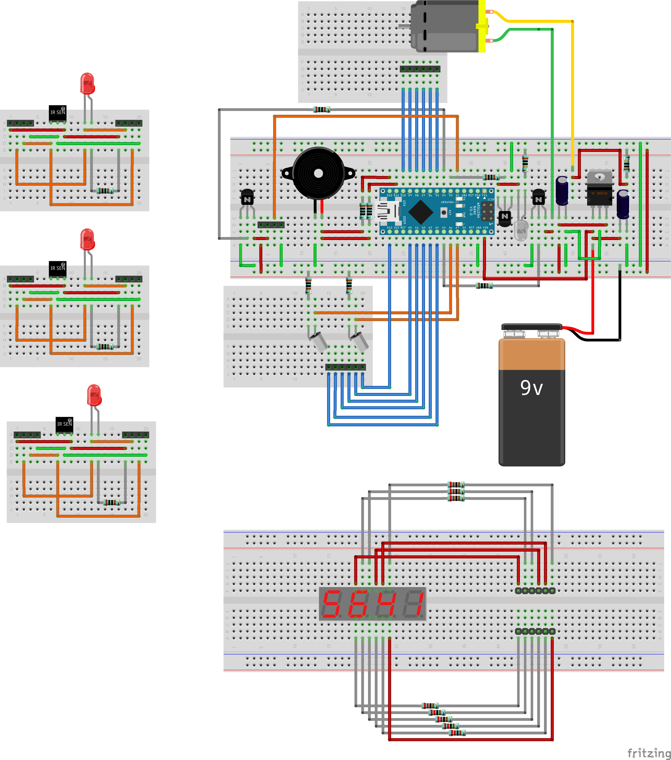
Next, a wiring diagram was made from the connections on the breadboard. It makes the wiring connections easier to read.

Finally the PCB board components were laid out. I used a ground fill to save as much etching as possible.
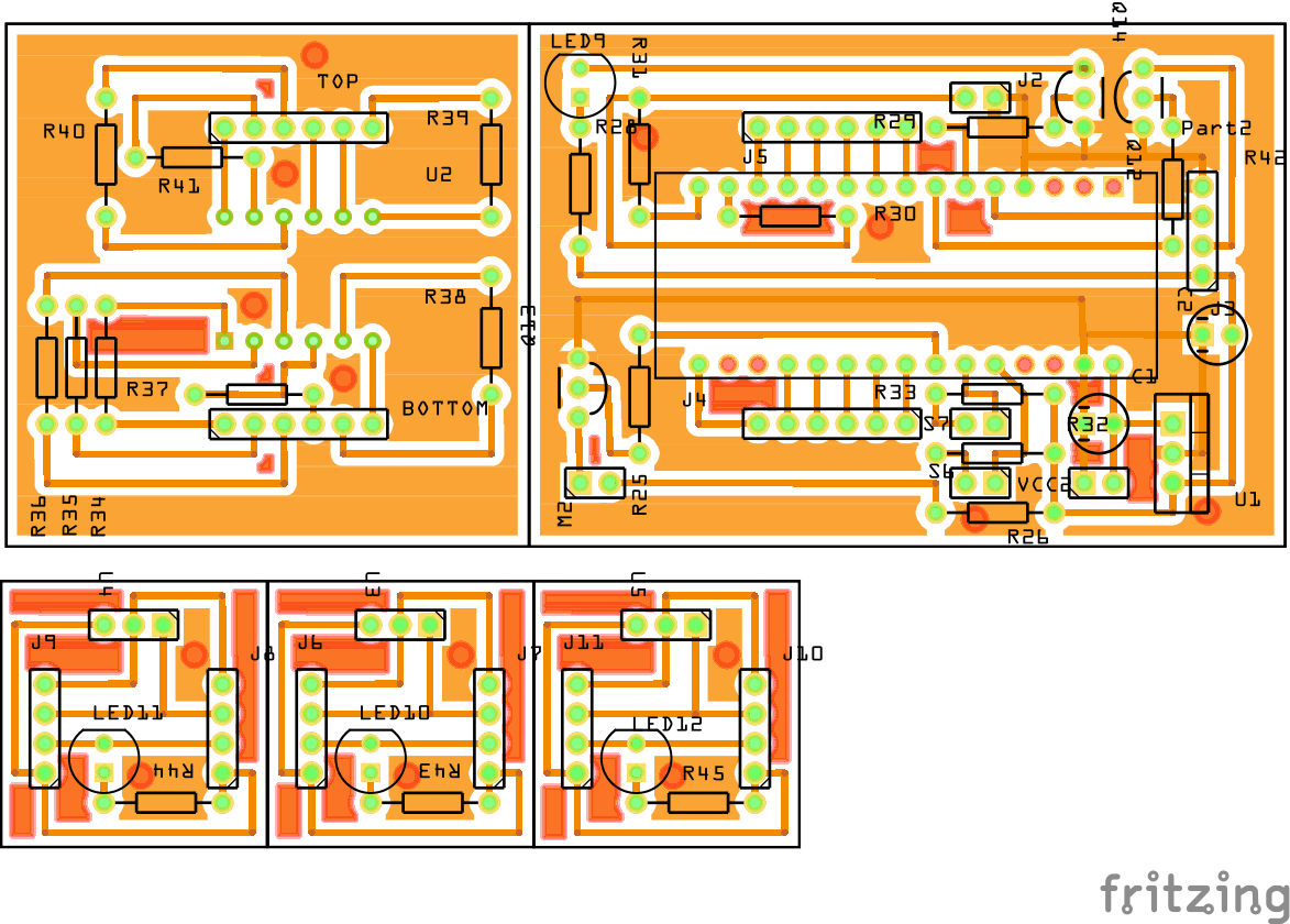
The final result.


