
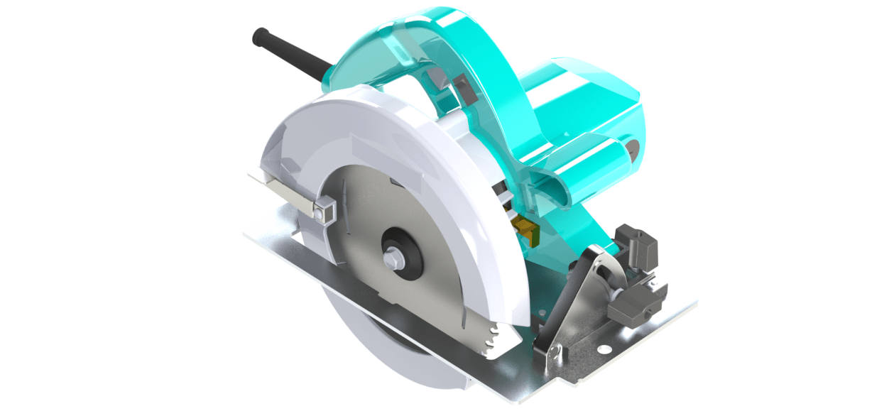
The image shown above is a computer generated rendering of a Makita 5007F Circular Saw. This was part of my CAD project at UVic where teams of three people (me, Josh Coutts, and Pelle Bjornert) take on the challenge of modelling a real life complex object in SolidWorks. This particular circular saw contains over 82 unique parts, irregular shaped motor housing features, and a large variety of locations where FEA could be applied
The Real Object
Just as a comparison on how accurate our model turned out to be, the image below is the original circular saw before it was taken apart.

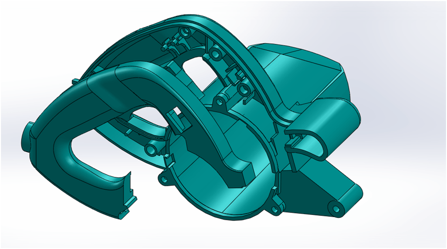
Surfacing
The irregular shape of the handle and the motor housing makes it a challenging set of objects to measure and shape in SolidWorks. Many surfacing techniques were used to get the exterior and interior features to be correct.
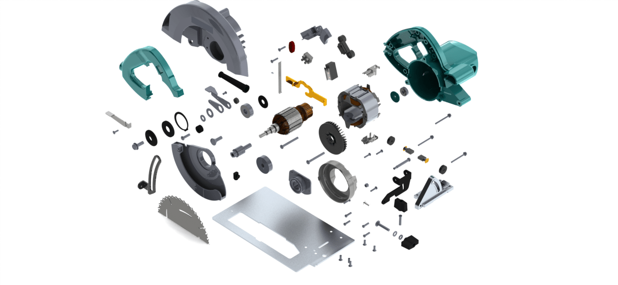
Assembly
With 82 different parts, the assembly for this project was particularly challenging. All the parts were numbered and named beforehand to avoid confusion between the other group members. While many of the mates in the final assembly were concentric, coincident or parallel, there were a few instances where trouble arose and complex mates were necessary.
Animation
There are instances were images are not enough to convey and visualize a final product. SolidWorks has a great animations tool that lets you animate the things you create. The video below shows the circular saw being taken apart.
Leave a Reply