
Software Flow Chart
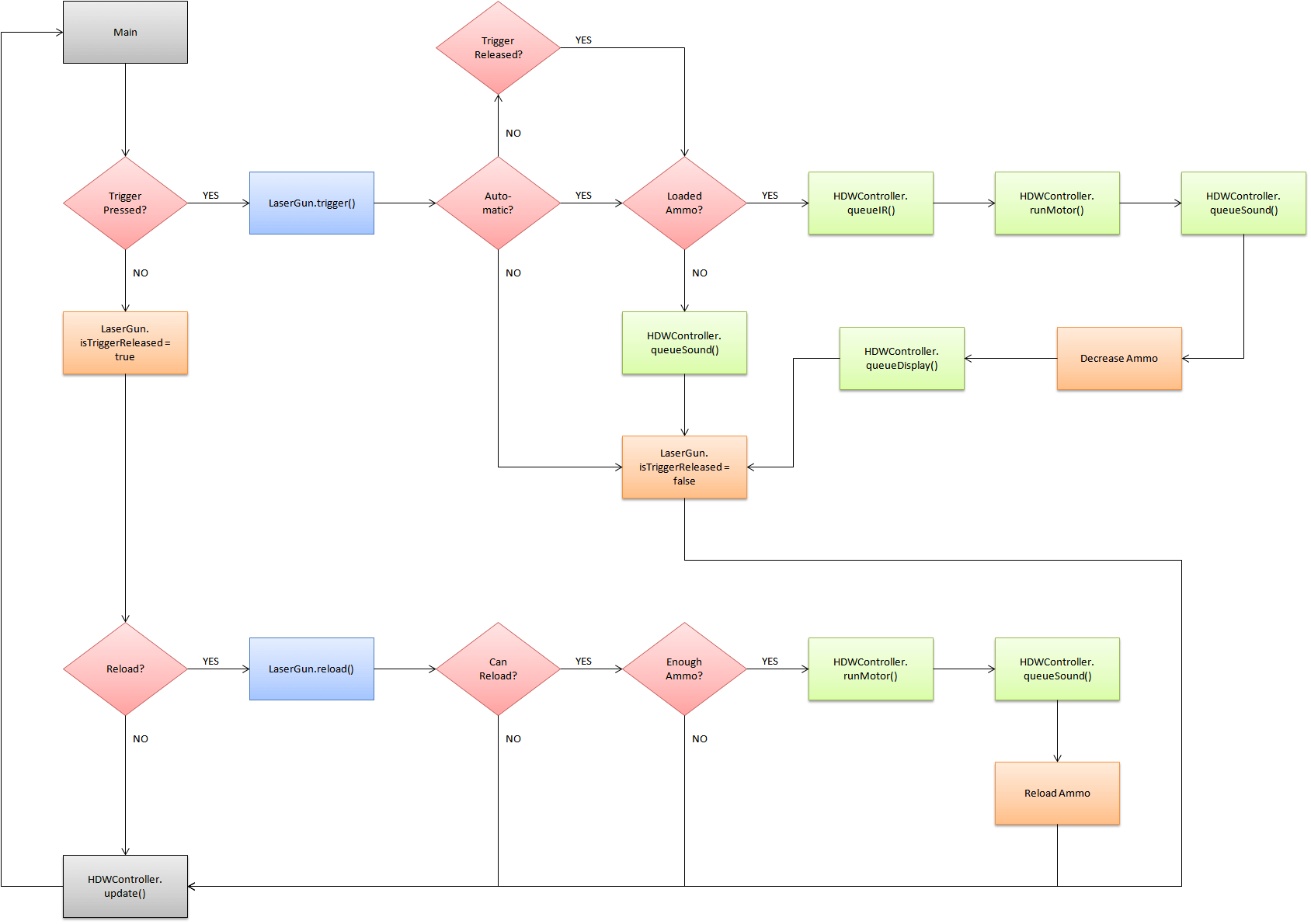
Over the holidays, I started drawing a flow chart diagram for the software portion of the Arduino Laser Tag project. The idea here is to use software polling to detect the trigger and reload buttons instead of using interrupts. I wanted to get around the issue of the interrupts incorrectly detecting the release of the trigger due to the debounce of the buttons. The HDWController will be a new class created to manage all the hardware components (motors, speaker, IR emmitter and sensor). The LaserGun class will be more of an abstract class that will queue certain tasks for the HDWController to perform. You can view the Excel spreadsheet of the flow chart here.
Leave a Reply